EZ Wizard: Assembly and prototyping
Getting started with the EZ MIDI Wizard programmer board
This page is for EZ Wizard assembly and prototyping. Details about programming are in the EZ MIDI Control user guide.
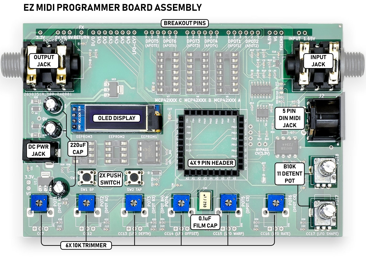
The highlighted parts are included but not assembled. You may want to use different parts. For example, instead of trimmers you might want to use 9mm pots. For the switches you might want to a switch you’d include in a finished build. Maybe you’d prefer a TSR jack for MIDI. The breakout pins included are single sided. Solder to the top for quick connect wires or solder to the bottom to plug into a breadboard. If you’d prefer double sided breakout pins you might like these extra long pins, or these male/female pins.
Four 9 pin headers are included to accommodate an EZ MIDI control board which is required for operation.
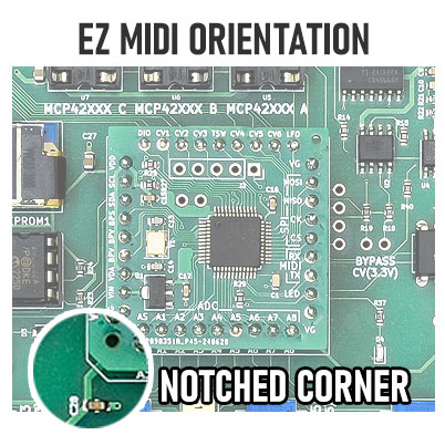
Plug in the EZ MIDI Control board
When inserting the EZ MIDI board be sure the corner notch is lined up with the outline on the programmer board.
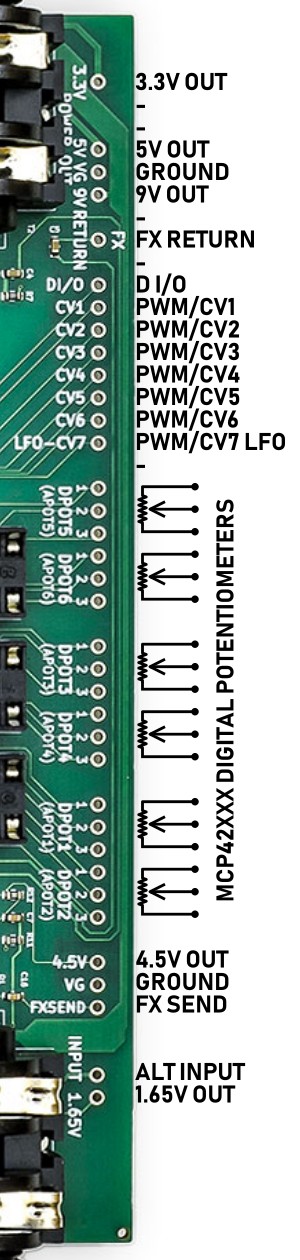
Breakout Pins
Power Pins: 9V OUT, 3.3V OUT 5V OUT & GROUND.
When using EZ Wizard for prototyping always draw power from the power pins. Using multiple power sources can create unwanted noise. EZ Wizard includes regulated on board 3.3v and 5v sources and filtered 9v. Filtering is via the 3 220u capacitors. You may find it necessary to add more filtering if your project spreads across multiple breadboards.
Effects Send and Return
EZ Wizard has an onboard bypass system based on an CD4066 analog switch IC. Just plug in your guitar and amp to the input and output jacks and send your input signal to your prototype circuit and return it to EZ Wizard. EZ MIDI also supports latching relay bypass, but is not included on EZ Wizard board.
PWM/Control Voltage Pins
These pins output a pulse width modulation (pwm) signal.
This is easily converted to a 0-3.3v control voltage via an RC filter.
PWM/CV7 is the LFO output.
Digital Pot Pins
Direct connection to digital pots. Sockets for MCP42xxx digital pot ICs are on the board.
Miscellaneous pins
DI/O Currently this pin is only used for EZ MIDI PRO.
4.5v Out: Bias voltage for the input buffer and CD4066 bypass. You can also use this as a bias voltage for your effect circuit.
1.65v Out: Buffered bias voltage for EZ MIDI control’s envelope detector. You can use this bias voltage on your effect circuit as well.
Alt Input: Same connection as the input jack.
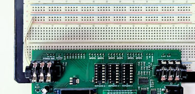
Breakout to Breadbaord
EZ Wizard plugs directly into a breadboard. We recommend either a double or triple breadboard. This gives you one section to manage connections, and keep your effects circuit separate.
In default operation Pot1 controls PWM/CV1 & digital pot 1. Pot2 controls PWM/cv2 & digital pot 2 and so on. All parameters are available via MIDI. Please see the user guide for more information on customizing EZ MIDI for your project.